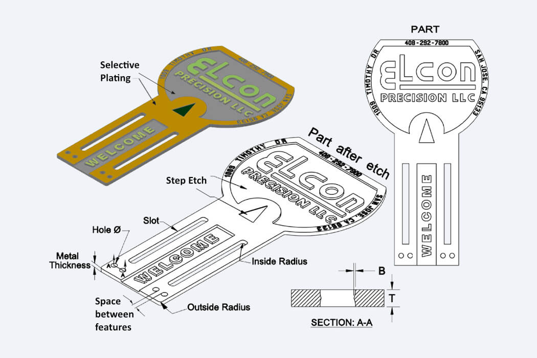
General Design Guidelines
- Inside radius = metal thickness
- Outside radius = 75% of metal thickness
- Hole diameter & slot = 120% Metal thickness
- Space between features = metal thickness
- Bevel (B) = 5% to 10% of metal thickness
- Step etch = 25% to 75% of metal thickness
Depending on the material and sheet size, our typical tolerances are:
| Metal Thickness (T) | Hole Diameter | Tolerance |
| 0.001 in. (0.025 mm) | 0.005 in. (0.127 mm) | ±0.0005 in. (0.012 mm) |
| 0.005 in. (0.127 mm) | 0.006 in. (0.152 mm) | ±0.001 in. (0.025 mm) |
| 0.007 in. (0.177 mm) | 0.008 in. (0.203 mm) | ±0.001 in. (0.038 mm) |
| 0.010 in. (0.254 mm) | 0.012 in. (0.304 mm) | ±0.002 in. (0.050 mm) |
| 0.020 in. (0.508 mm) | 0.024 in. (0.609 mm) | ±0.003 in. (0.076 mm) |
Although tighter tolerances can be achieved, feature dimensions are typically 1.2x material thickness and tolerances are 10%-15% of material thickness. Contact us today for more information or if you have any questions!
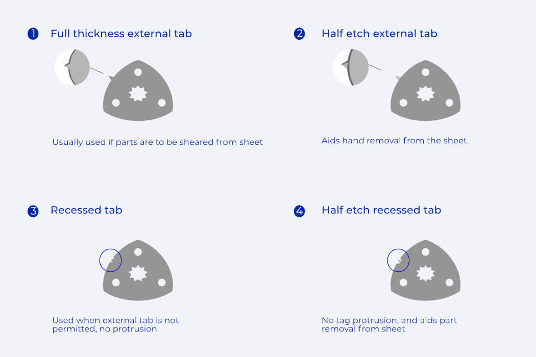
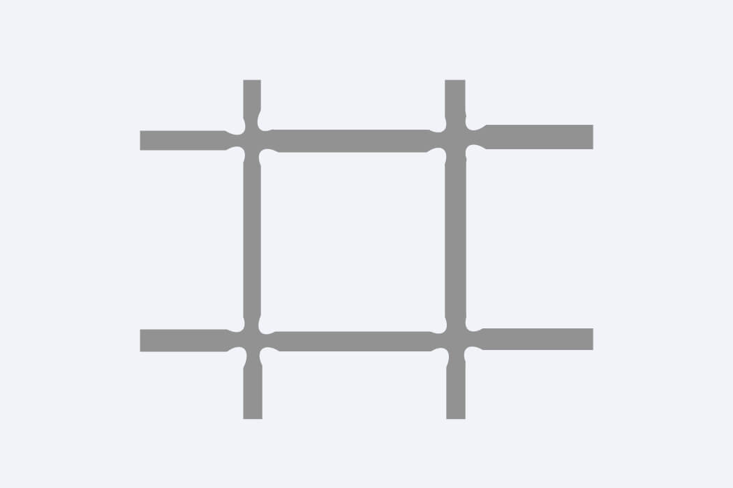
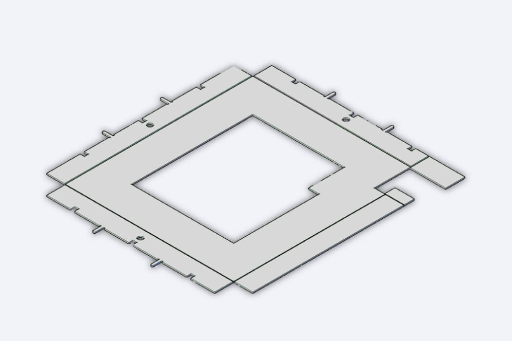
Tabbing
To allow for tighter tolerances, faster inspection, easier storage, safer handling and plating, we recommend that parts be left in the sheets during and after production. Doing so requires a tab be connected to the individual parts so that they stay on the sheet for easy removal after manufacturing is complete.
In instances where tabs may interfere with the function of the part, they can be etched as “dropouts”, or individual parts.
Parts that have tabs can be removed by hand or by shearing. If parts are to be sheared they must have outboard tabs. The chart below shows the minimum size of these tabs.
|
|
Metal Thickness |
Minimum Length |
|
Single Shear |
.005 in. to .015 in. |
.003 in. |
|
Double Shear |
.005 in. to .015 in. |
.002 in. |
Rounded Interior Corners
Etching a rectangle creates inside corners that are rounded. If relief is needed in the corners to fit a square-cornered part, this can be done by etching into the corners slightly beyond the edges of the rectangles.
Bend lines
To allow sidewalls of a shield to be bent, transforming the component from a 2D structure to a 3D structure without the need for forming tooling, Elcon can incorporate bend lines into the component.
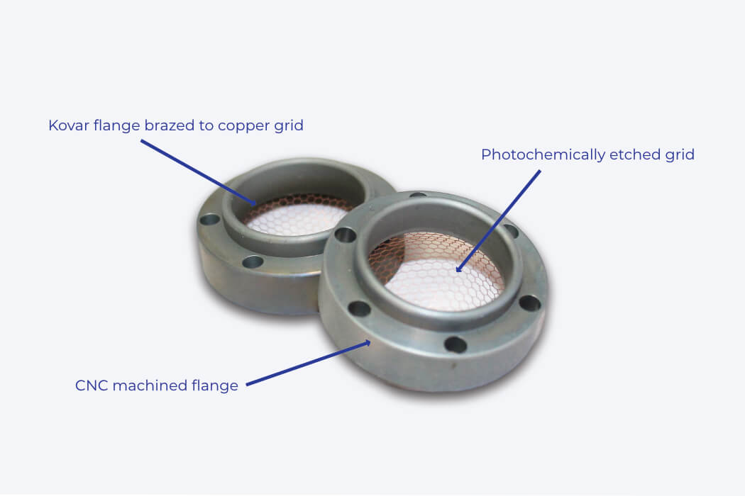
Combine multiple services
Elcon offers a one stop shop experience. Depending on what your requirements are, our engineers will work with you to determine what processes are suitable. To reduce cost and production time as well as meet design specifications, a 2D unit can be photochemically etched, then brazed to a CNC machined part to form the desired 3D component. Whatever your part, we’ll work with you to find the best solution.